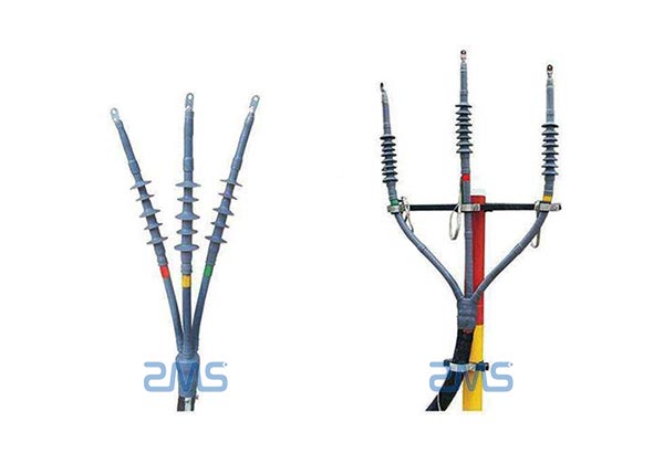
Cable termination and joints are a very important process in cable construction, and the quality of cable termination and joints directly affects the quality of the entire electrical engineering construction.
Therefore, in the process of cable construction, we must conduct a comprehensive analysis of all aspects of the cable to ensure that the cable can work effectively and stably for a long time, which is also the main role of cable termination and joint work.
1. Characteristics Of Cable Termination Joints
At present, when carrying out cable construction, cable accessories mainly use chemical synthetic materials as the insulation material for cable termination. This material is mainly based on the method of applying high-quality rubber insulation, which is scientifically processed so that the original rubber material with good hydrophobicity can be further developed. It also greatly improves its self-healing property, and when water drops appear on this rubber material, it automatically generates a release point film to prevent the aging of the material caused by long-term use.
Therefore, it can be seen that the cable attachment has several characteristics: insulation performance, corrosion resistance, water resistance, and some materials also have anti-UV characteristics, so it has a very long service life.

2. The Role Of Cable Termination Joint Kits
In fact, the role of different cable termination joints is very simple, which is to play a connecting role and stabilizing role. Let the voltage from the high voltage to the bottom end of the cable a certain, so as to achieve a stable state. Make its various terminals power plant axis stress and to the stress development of a certain change, so as to achieve a continuous cable.
In cable construction, the cable is mainly composed of three aspects: conductor, insulation, sheathing, and shielding, while the cable termination is made to continue its cable function through its own connection and stabilization.
In cable construction, the manufacturing process of cable terminations is unique from other electrical component manufacturing plants. In addition to ensuring its own stability, it is also necessary to ensure the insulation of the cable accessories to ensure that no problems will arise in the long-lasting power use. And super waterproof, but also can significantly improve the service life of the cable.
3. The Installation Requirements Of Cable Termination And Joints
3.1 If the single-core cable is shielded by copper wire, it is tied with bare copper wire and then the shielded copper wire is turned to the back and left as a bridging wire.
3.2 For single-phase direct burial laying, ferromagnetic material cannot be used as a protection box, and it is recommended to use glass fiber reinforced plastic or rigid plastic protection box.
Different from the traditional cable accessory construction process, the prefabricated cable termination construction process is complicated and technically difficult. Its installation procedures and process requirements are not easily mastered by the construction personnel, and one or other problems are common in the construction. This is the main factor affecting the correct installation and safe operation of the cable branch box.
The cable needs to determine the cable termination or cable joint length by various technical means during the installation. Cable termination or connector length is appropriate, flush, to prevent the cable from being too long or too short to produce a large thrust or pull force, resulting in fixed T-shaped cable joints and cable or cable tap box out of poor contact with the casing, to avoid the cable tap box out of the casing due to the force resulting in air leakage.
The cable tap box base must be installed within the cable fixing bracket, cable pericentric points get along with the following in the bracket for fixed processing. At the same time, measures should be taken to ensure that the trigeminal head in the terminal column is below, to ensure that no tap box within the cable and accessories is subject to downward pull, which can effectively avoid the cable tap box out of the line casing due to the force leading to gas leakage phenomenon.

3.3 conductor connection tube set in the stripped long end of the cable core conductor, first crimp good, remove burrs and flying edge, remove metal shavings, wipe the cable insulation surface, semi-conductive layer surface, and conductor connection tube surface with a clean cloth.
3.4 Pre-set joint prefabricated parts. First, in the stripped long end of the cable insulation surface, the surface of the semi-conducting layer and the joint prefabricated inner hole is evenly coated – a layer of silicone grease. Then set on the core, until the cable insulation from the other end of the prefabricated parts is exposed.
3.5 Crimp the other end of the core. The connector outer sheath tube is on the short end of the stripped-4 cable and in each phase of the core on the E shielding copper wire mesh. Then insert each phase of the short end of the cable core conductor into the long end of the cable that has been crimped in each phase of the core -9- ~ ~ connection tube, crimp, remove the flying edge, and burr. Clean the cable insulation surface, semi-conducting layer surface, and conductor connection tube surface with a clean cloth.
3.6 Move the cable joint prefabricated parts to the joint position. Apply a layer of silicone grease evenly on the insulating surface of the short end of the cable, and then pull the joint prefabricated part of the collar on the core of the long end of the cable to the joint position. To ensure that the stress cone semi-conducting layer of the two ends of the prefabricated parts just laps in the two ends of the cable insulation on the end of the semi-conducting layer respectively. Specific size according to the installation instructions provided by the manufacturer.
3.7 in the cable core insulation semi-conducting layer and prefabricated YC – ~ conductive layer lap wrapped around the semi-conducting self-adhesive tape to form a continuous cone transition surface.
3.8 The shielding copper wire mesh is moved to the middle of the joint, evenly stretched to both ends, so that it is tightly attached to the surface of the prefabricated joint, and both ends are tied and welded to the cable shielding copper tape. The shielding copper wire mesh can also be applied by winding.
3.9 Pinch the three-phase connectors together, and then tie the bridging wire (tinned braided copper wire) to the steel tape of the cable and the three cores shielding steel tape at both ends of the connector respectively, and solder firmly.
Tie the three-phase connector with white yarn tape or PVC tape, and fill the three-phase gap with the filler to make it as round as possible.
4. Notes On The Installation Of Cable Termination
In the construction of the cable termination, the size of the prefabricated cable accessories must be exploited in strict accordance with the installation instructions. The cable termination construction dimensions required by T-type cable joint products of different manufacturers are slightly different. Construction cannot be carried out according to traditional cable termination assembly dimensions or exploitation dimensions of other manufacturers.
The construction process should ensure that the cable termination copper shield layer, semi-conducting layer, and insulation layer construction stripping cut size is correct. Otherwise, too much or too little of the outer semi-conducting layer and copper shield layer of the cable are retained, and the length of the insulation part is too long or insufficient.
ZMS Cable Company is a leading manufacturer of high-quality cables and cable accessories for a wide range of applications. With over 20 years of experience in the industry, we have developed a reputation for excellence and reliability. Our state-of-the-art production facilities and skilled team of engineers and technicians allow us to produce cables that meet the highest standards of performance and durability.
