With the continuous upgrading and construction of power grids and transportation infrastructure, transmission lines “three across” related issues are becoming more frequent. Such as improper handling, which will likely lead to significant public safety and grid security incidents. So for the transmission lines “three across” section, construction standards and other aspects must be strictly controlled. This paper provides a summary of this issue.
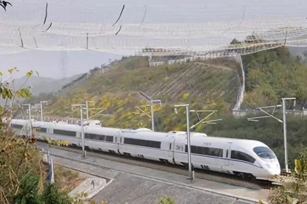
1. Preface
In the power grid construction project, we often encounter transmission lines and railroads, highways, power lines, and other important facilities crossing (near), such issues belong to the project’s key control indicators, such as improper handling. And it will probably lead to the occurrence of large public safety and grid security events. To ensure the safety of the power grid and its cross (near) facilities, the power grid and railroads, highways, and other departments have issued regulations, specifications, and industry regulations for the above-mentioned issues. Following, taking into account the requirements of the power and related departments, this paper provides a summary of this issue.
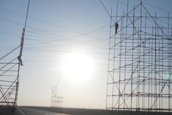
2. What is the “three-span”?
“Three-span”: refers to the section where the transmission and distribution line spans railways, first-class and above highways, and important transmission channels.
Among them, railways include high-speed railways, express railways, electric ordinary-speed railways, and fuel (gas) ordinary-speed railways. First-class and above roads include first-class roads and expressways (national expressways, local expressways).
The important transmission channel consists of several important transmission lines, which are divided into the national (South) grid company level and the provincial company level. Significant transmission lines are composed of overhead transmission lines and strategic overhead transmission lines that constitute the core backbone grid.
Core backbone network frame, including AC and DC UHV power grids. Each substation of 500kV and 750kV shall have at least one outgoing line to form the minimum backbone grid of the power grid. 330kV and 220kV substations supplying power to secondary loads and above shall have at least one line connected to the main network.
Strategic transmission lines, including large-scale hydropower, coal power, and nuclear power transmission overhead lines. Transnational networking overhead transmission lines. Cross-regional networking overhead transmission lines.
The important transmission channels at the company level of the State (South) Power Grid include channels composed of UHV AC and DC transmission lines. A channel is composed of two or more significant transmission lines whose center distance generally does not exceed 600 m. When the lines in the channel fail at the same time, it constitutes a regional or provincial power grid event of level 3 and above.
The provincial company-level important transmission channel consists of two or more important transmission lines whose center distance is generally not more than 600 m. When the lines in the channel fail at the same time, it constitutes a four-level regional or provincial power grid event.
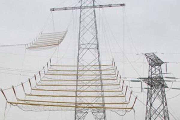
3. General requirements for “three-span”
(1) When selecting the line path, the number of “three spans” should be reduced, and it should not be spanned continuously. When crossing important transmission channels, it is not suitable to cross two or more transmission lines in one gear, and it is not suitable to cross at the top of the tower.
(2) The intersection angle between the “three-span” line and the high-speed rail should not be less than 45°, it should not be less than 30° in difficult cases, and it should not cross within the exit signal of the railway station. The intersection angle with the expressway should generally not be less than 45°. The intersection angle with important transmission channels should not be less than 30°.
(3) The “three-span” should try to avoid the situation of large span and large height difference, and the ratio of spans on both sides of the spanning tower should not exceed 2:1.
(4) “Three spans” should be spanned by independent tension sections with no more than 3 bases of square towers. The important factor of the tower structure should not be lower than 1.1. In addition to the anti-theft measures, the tower should also adopt the whole tower anti-loosening measures. When crossing important transmission channels, the design standard of crossing lines should not be lower than the lines being crossed.
(5) For the “three-span” towers in the ice area of 15mm and above, the ice-covered load of the towers shall be checked and calculated according to the provisions of Article 10.1.12 of “Code for Design of 110kV-750kV Overhead Transmission Lines” (GB 50545-2010). Among them, the newly-built line crosses over with expressways and electrified railways, and the design icing of the spanning gear should be 5 mm higher than that of the towers in the same area. For the areas where over-design icing has occurred in history, the calculation should also be carried out according to the rare icing conditions.
(6) The pendant insulator strings of “three-span” lines of 500kV and below shall adopt an independent double-string design. For lines with a large height difference in mountainous areas and continue going up and down mountains, a single hanging point double connection can be used, and the tensile insulator should be in double connection or above structure. The “three-span” ground wire suspension should be designed with independent double strings, and the tensile string connection hardware should be increased by one strength level.
(7) The pre-twisted anti-vibration hammer should be used in the “three-span” section. Wear-resistant connection fittings should be used for the “three-span” conductors in the areas with severe wind vibration and easy dancing.
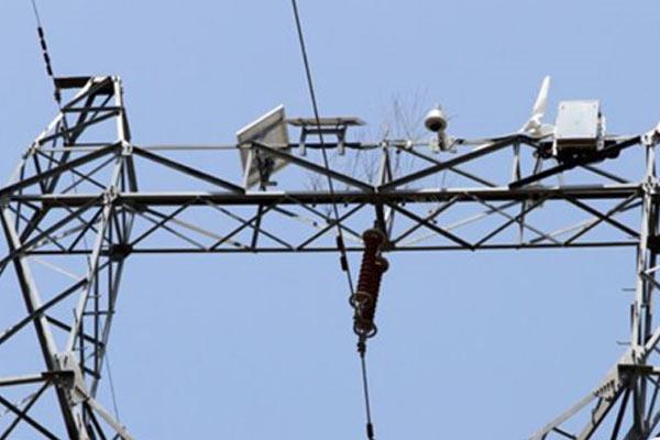
(8) Distributed fault diagnosis devices and video monitoring devices should be installed when crossing high-speed railways. Image or video surveillance devices should be installed when crossing highways and important power transmission channels.
(9) The “three-span” ground wire should be made of an aluminum-clad steel strand (the diameter of the single wire is not less than 3.0 mm), and the optical cable should be an OPGW optical cable with an all-aluminum-clad steel structure.
(10) For the “three-span” UHV line, the ground wire in the span should not have a joint. For other voltage levels “three-span”, the ground wire in the tensile section should not have joints.
(11) The “three-span” fittings of transmission lines with voltage levels of 750kV and below shall be checked for crimping quality one by one following the construction acceptance regulations. And carry out X-ray non-destructive testing according to the proportion of 10% of the total number of tension clamps in the “three-span” section.
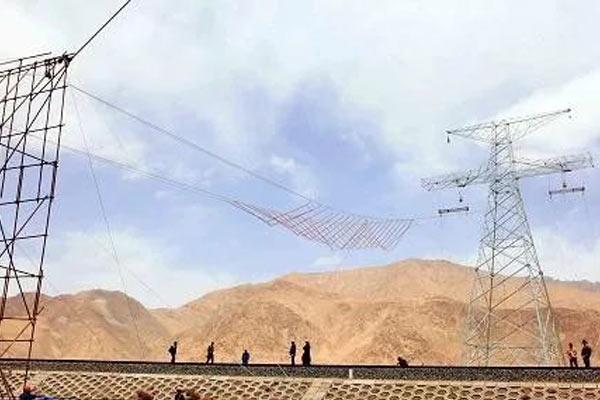
4. Specific requirements for “three spans”
4.1 Crossing the railway
(1) Power lines and communication lines of 6kV and below shall not cross over railway lines and railway 10kV power feed-through lines.
Power lines below 35kV shall not cross over the catenary and its power supply lines in the electrified section. Power lines below 10kV shall not cross over the catenary of ordinary electrified railways and their power supply lines.
When the above-mentioned power lines need to cross the railway, cables must be used to cross the railway subgrade. The buried depth should be below 1.5 m on the road surface, and a protective metal casing or concrete casing should be provided.
(2) Regardless of the voltage level, the power lines should not cross over the railway station.
(3) For local power lines crossing electrified railways, under the most unfavorable climatic conditions, the minimum clear height of the railway catenary bearing cable when the maximum sag is:
35kV and above to 110kV power lines not less than 3 m. The 220kV power line shall not be less than 4 m. The 330kV power line shall not be less than 5 m. The 500kV power line shall not be less than 6 m.
(4) For power lines crossing non-electrified railways, under the most unfavorable weather conditions, the minimum clear height of the maximum sag from the top surface of the railway rails: 110kV and below power lines, not less than 7.5 m. 220kV power line, no less than 8.5 m. 330kV power line, no less than 9.5 m. 500kV power line, no less than 14.0 m. When the railway has electrification planning, it shall be implemented according to electrified railway standards.
(5) For the power line towers (both sides of the railway) that cross the non-electrified railway, the horizontal distance from the railway (quasi-meter-gauge railway, the same below) adjacent to the rail is not less than the pole height plus 3.1 m. When crossing an electrified railway, the height of the pole shall not be less than 5 m. If it cannot meet the requirements, it can be appropriately reduced, but it shall not be less than 30 m.
(6) Power lines of 110kV and below across the railway must be spanned independently. Power lines of 220kV and above should be spanned independently.
(7) The conductor and ground wires (lightning protection wires) of the power lines crossing the railway shall have no joints, and the mechanical strength shall comply with the national power design specifications. The conductors should be suspended in a “double-fixed” (double-string insulator suspension).
(8) The wind load and ice load of the power line crossing the railway shall be checked according to the following provisions:
15 years for transmission lines below 110kV. 110 ~ 330kV transmission lines according to 30 years. 50 years for transmission lines of 500kV and above.
4.2 Crossing the highway
(1) across the file should be used straight-line tower not more than 3 bases of independent tension-resistant section.
(2) each voltage level overhead lines across the road, the minimum vertical distance from the conductor to the road, crossover angle. The minimum horizontal distance from the outer edge of the tower to the outer edge of the roadbed should meet the latest line design standards (see schedule).
(3) the power line shall not intrude into the highway building boundaries, shall not impede road traffic safety and personnel safety, and shall not damage the structure of the highway and facilities. Highway Safety Protection Regulations, Chapter II, Article 11 provides that the scope of the highway construction control area, from the outer edge of the highway land outward distance standard: not less than 20 meters for national roads; provincial roads not less than 15 meters. County roads are not less than 10 meters. Country roads are not less than 5 meters. Belonging to the highway, the scope of the highway construction control area from the outer edge of the highway land an outward distance standard of not less than 30 meters.
(4) new, modified (expansion) lines are prohibited in the middle of the highway (including the green belt) to set up towers.
(5) across the urban expressway and trunk road design standards should be no less than the standard implementation across the first-class highway.
(6) tower structure importance factor should be taken 1.1.
(7) across, transmission lines and highway crossover angle should not be less than 45 °.
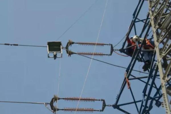
(8) across the section insulator string using double hanging points, double “I” string, or “V” string type.
(9) across the file within the conductor ground line does not allow joints.
4.3 Crossing important transmission channels
4.3.1 General requirements for overhead lines spanning 110kV and above
(1) When crossing important power lines, it is not suitable to cross at the top of the tower. An independent tension section should be used, and the length of the independent tension section should not be greater than 3.0 km.
(2) The newly-built important transmission line channels should avoid the entry and exit lines of 500kV and 220kV substations (including planned substations) as much as possible (except for the transmission lines that need to be connected to the 500kV and 220kV substations).
(3) When the new line needs the cable to drill through the important transmission line channel, and the path is single, and the new line will also pass through this place in the future, it is recommended that the civil works should be completed at one time in the final stage, and the construction type of the power channel should be selected according to the final scale form.
(4) During the comparison and selection of the grid planning scheme, the crossing of important power lines should be taken as one of the comparison and selection factors of the planning scheme. In the case of basic technical and economic parity, priority is given to network solutions that do not cross important power lines.
(5) When planning the access plan of the new substation, try to avoid the crossing of all overhead outgoing lines and important power lines. In particular, avoid repeated crossing of lines of different voltage levels and essential power lines.
(6) Minimize and avoid crossover between transmission lines. When selecting the address of the new substation and determining the layout plan of the power distribution device, deeply optimize the outgoing direction and arrangement order of the lines of each voltage level. Avoid and reduce the intersection between lines from the layout of the outgoing line. For lines that may cross over in the future, the location of the crossing point should be reserved in advance in combination with long-term planning. On the premise that the line of low voltage level meets the regulations, the distance to the ground should be as low as possible. To facilitate the crossing of high-voltage grade lines. High-voltage lines should reserve as high a distance to the ground as possible to facilitate the drilling of low-voltage lines. For those that must cross over the line, adopt the method of crossing one line in one gear, and try to avoid multiple crossings in one gear.
4.3.2 Special requirements for crossing 500kV transmission lines
(1) The crossing position should be reasonably selected according to the route path, topographic features, construction method, etc., and the tower top crossing should be avoided.
(2) When continuously crossing multiple parallel lines, when conditions permit, it is advisable to reasonably select crossing points between parallel lines, and set up tension towers (or straight towers) to reduce the number of crossing lines in the same gear.
(3) Considering the setting of the stretch field comprehensively, to shorten the spanning construction time, the spanning of the independent tension section should be adopted when spanning the 500kV line. And the spanning plan should be reasonably determined according to the terrain, features, and other conditions. Can adopt “resistance-straight-straight-resistance”, “resistance-straight-resistance”, “resistance-straight-straight-straight-resistance” scheme. In addition, the linear tower should not exceed 3 bases, and the length of the spanning tension section should generally not be greater than 3.0 km and should be shortened as much as possible when conditions permit.
(4) The intersection angle between the line and the 500kV power line should not be less than 45°, and the spanning span should be shortened as much as possible when the limited section cannot be satisfied.
(5) When using the non-straddle frame to cross the wire without power failure, the spanning span should be reduced as much as possible, and the spanning span can be controlled at not more than 300 m. When it cannot be satisfied, consider using a base spanning tower close to the line to be spanned to support the spanning network, etc., to realize the spanning without power failure.
(6) In addition to meeting the safety distance specified in the specification, the construction safety distances such as foundation excavation, tower assembly, and cross arm hoisting should also be considered when crossing the tower and the side conductors of the line to be crossed. When conditions permit, the minimum horizontal distance of the wire across the tower position shall not be less than the height of the crossing tower.
(7) There should be no joints between the inner conductor and the ground wire of the spanning gear.
(8) All aluminum-clad steel types should be used when the ground wire adopts OPGW optical cable.
(9) Independent double hanging points, double “I” type or double “V” type strings should be used for the insulator strings in the spanning gear.
(10) The first metal fitting connected with the cross arm should be flexible in rotation and reasonable in force. Its strength should be higher than that of other hardware in the string.
(11) The ground wire clips, anti-vibration hammers and spacers whose spanning position are in the area with severe wind vibration should use reinforced fittings or pre-twisted fittings.
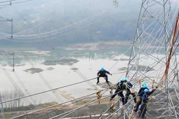
(12) When setting up auxiliary cross-arms across towers or independent auxiliary towers for construction, the scheme of setting up auxiliary cross-arms across towers should be adopted.
(13) The spanning tower (including the auxiliary cross arm) and the independent auxiliary tower shall meet the construction load requirements of the line spanning.
(14) The position of the auxiliary cross arm across the tower shall meet the requirements of the shielding width of the construction and installation of the capping net. And it should be set in the tower section to reserve the installation hole.
(15) The tower that spans the tension section should not use the cable tower.
(16) The height of the ground wire of the line being crossed should be calculated according to the minimum sag condition, and the lowest temperature condition is generally selected.
4.3.3 Crossing 220kV and 110kV transmission lines special requirements
(1) combined with the line path, terrain and landscape features, construction methods, etc. Reasonable choice of crossing location, it is desirable to avoid the top of the tower across.
(2) when crossing multiple parallel lines in succession, when conditions allow, it is appropriate to reasonably select the crossing point between parallel lines. Set up the tension-resistant tower (or linear tower), and reduce the number of lines spanned within the same file.
(3) comprehensive consideration of the draft field settings, to shorten the construction time across, across the tension section length should generally not be greater than 3.0 km, as short as possible when the conditions allow.
(4) line and 220kV and 110kV power line crossover angle should not be less than 15°. For restricted lots can not meet when it should try to reduce the file distance.
(5) when using no span frame non-stop across the line construction, should try to reduce the span file distance, span file distance can be controlled by not more than 400 m. When can not meet, can consider using a base near the span of the line across the tower support across the network, etc., to achieve non-stop across?
(6) across the cable tower and the side of the line to be crossed in addition to meeting the safety distance specified in the specification. Should also consider the foundation excavation, tower set up, cross-arms lifting, and other construction safety distances.
(7) across the file within the guide ground line should not have joints.
(8) the ground line using OPGW optical cable should be used when the full aluminum-clad steel type.
(9) across the file insulator string should be used independent double hanging point, double “I” type or double “V” type string, “V” type string fixture should be used to prevent falling off the pin, priority is given to L type pin.
(10) The first gold fixture connected with the crossbar should be flexible and reasonably stressed. Its strength should be higher than the strength of other fixtures in the string.
(11) across the location in the wind vibration serious areas of the guide wire clamps, anti-vibration hammer, and spacer bar should be selected to strengthen the type of gold or pre-stranded gold.
(12) across the tower set up auxiliary cross-arms or independent auxiliary towers are constructed. Should be used across the tower set auxiliary cross-beam program.
(13) across the tower (including auxiliary cross-arms), an independent auxiliary tower should meet the line across the construction load requirements.
(14) across the tower auxiliary cross-beam position should meet the construction and installation of capping network shielding width requirements. And should be set in the tower section stay installation hole.
(15) across the tension-resistant section of the tower should not be used to pull the line tower (or pole).
(16) is across the line of the ground line height should be calculated according to the minimum arc drape conditions, generally preferable to choose the lowest temperature conditions.
5. Conclusion
The above overhead transmission line “three spans” from the design, and construction has been briefly summarized, the strict implementation of these standards will provide a basic guarantee for the “three spans” safety. In addition, the “three spans” of the operation and inspection are equally important. Only the establishment of a scientific, comprehensive, and strict operation and inspection system, through the continuous investigation of deficiencies, can further fundamentally ensure the absolute safety of the power grid and its crossings.
In short, the transmission line “three across” problem is seriously related to the grid and public safety, and can not be sloppy. Grid construction must be from the design, construction, operation, inspection, and other aspects of the whole process of strict control, pay close attention to ensure that nothing is wrong!
