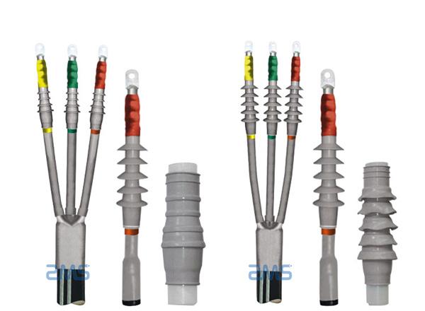
1 Scope of application
It is suitable for the installation of 10kV XLPE cable cold shrink termination and joints in distribution network projects.
2 Design requirements
2.1 Process requirements for finished products
There is a good electrical connection between the core of the cable head and the termination. The inner sheath, shielding layer, insulating layer, and conductor after stripping is not damaged. The grounding wire is firmly connected. The cable accessories are installed with perfect and reliable sealing and fixing. The gold of the cable has sufficient mechanical strength.
2.2 Cable termination
(1) The 10kV cable termination shall meet the following requirements:
a) Outdoor cable terminations should be used when used outdoors, and cold-shrinkable cable terminations should be used when the ambient temperature difference is large.
b) Choose indoor cable terminations when used indoors.
c) The cable termination accessory grade uses a voltage grade of 15kV.
d) The pipe diameter of the cable accessories needs to correspond to the core section of the cable.
(2) For cable terminations where inflammable and explosive places are not allowed to have a fire, cold shrinkable cable termination accessories should be used.
(3) The cable termination should adopt measures such as reinforced insulation, sealing moisture-proof, mechanical protection, etc. And It should have effective measures to improve the electric field concentration at the cable shielding end and ensure the distance between the outer insulation and the ground.
2.3 The metal sheath of the cable
(1) The metal layer of the power cable must be directly grounded. The metal layer of the three-core cable in the AC system should be grounded at the cable line terminations and joints.
(2) If the line is not long, it should be directly grounded at one end of the line.
(3) When the line is long, it can be directly grounded at both ends of the cable.
2.4 Cable termination bracket
(1) The structure of the termination bracket should be conducive to the installation of cables and their components: when the working current is greater than 1500A, the structure of the bracket should have additional heating measures such as preventing the closure of the transverse magnetic circuit.
(2) The distance between the metal parts of the cable termination (including the shielding cover) between the conductors of different phases and between the conductors of each phase to the ground is in line with the safe clearance of indoor and outdoor power distribution devices.
(3) The termination bracket must have sufficient mechanical strength to support the full load of the termination and the temporary additional load during installation and maintenance (considered as 2 kN).
(4) Outdoor termination brackets made of profiles should be hot-dip galvanized.
(5) The termination bracket must be reliably connected to the grounding grid.
(6) Copper terminals are generally used for wiring terminals, which are selected according to the cross-section of the cable core.
2.5 Control Points for Cable Termination Installation Design Requirements
Process: Design requirements control point
Cable core connection: When the core is crimped, after crimping the mold, keep the pressure for 10 to 15 seconds
Metal sheath grounding wire installation: The connection between the copper shielding grounding wire and the steel ground wire should be staggered, so that the two grounding wires will not touch each other.
3 Key points of construction technology
(1) The three-core power cable is located at the cable termination, and the cable armor and metal shielding layer should be led out separately by grounding wires and should be well-grounded. The external connection of the grounding wire of the armored and the metal shielding layer should be staggered at an angle, and the two grounding wires should not touch each other.
(2) When making 6kV and above cable terminations outdoors, the relative humidity of the air should be 70% and below. When the humidity is high, the ambient temperature can be increased or the cable can be heated.
(3) When making plastic insulated power cable terminations, dust and debris should be prevented from falling into the insulation. Construction in fog or rain is strictly prohibited.
(4) The cable core connection fittings should use standard connecting tubes and terminations, the inner diameter should match the cable core, and the gap should not be too large. The cross-section should be 1.2 to 1.5 times the cross-section of the core. When crimping, crimp pliers and dies should meet specifications.
(5) Before making cable joints, you should be familiar with the installation process data, do a good job in inspection, and meet the following requirements:
a) The cable insulation is in good condition and has no moisture. No water should enter the plastic cable. If it is found that the inside of the cable is damp and water, the installation should be stopped, and the installation can be continued after drying.
b) The specifications of the accessories should be consistent with the cables. The parts should be complete without damage. The insulating material should not be damp. The sealing material should not fail.
c) The construction equipment is complete, easy to operate, the condition is clean, and the consumable materials are complete. The solvent for cleaning the plastic insulating surface should be prepared in accordance with the process guidelines.
(6) The grounding wire of the power cable should use copper-stranded wire or tinned copper braided wire to connect with the cable shielding layer. If the cross-section of the cable core is below 150mm2, the cross-section of the copper stranded wire or tinned copper braided wire should be 16mm2. If the cross-section of the cable core is more than 150mm2, use 25mm2 copper stranded wire or tinned copper braided wire.
(7) When making cable joints, it should be operated continuously from the beginning of stripping and cutting the cable until it is completed, to shorten the insulation exposure time. The core wires and remaining insulation should not be damaged when stripping the cable. Wrapping, fitting, shrinking, etc. of supplementary insulation shall be cleaned.
(8) When the cable core is connected, the oil stain and oxide layer on the inner wall of the core and the connecting pipe should be removed. The crimping die and fittings should be properly matched. The compression ratio should meet the requirements of the compression process. After crimping, the bumps on the termination or connecting tube should be repaired and smooth, and no burrs should remain.
(9) The metal sheath at the termination of the three-core power cable must be well-grounded. The copper shield and a steel wire of each phase of the plastic cable should be firmly grounded. When the cable passes through the zero-sequence current transformer, the metal sheath of the cable and the grounding wire is insulated to the ground. When the grounding point of the cable is above the transformer, the grounding wire should be grounded through the transformer.
(10) When assembling and assembling cable terminations, measures of plugging, moisture-proof and sealing must be taken for the cooperation or overlap between the components. Plastic cables should be sealed with self-adhesive tapes, adhesive tapes, adhesives, etc. The surface of the plastic sheath should be roughened, the bonding surface should be cleaned with solvent to remove oil stains, and the bonding should be good. There should be no leakage from the cable termination.
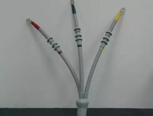
(11) There should be obvious phase-color marks on the cable terminations, which should be consistent with the phase of the system.
(12) Peeling of sheath layer and armor layer
a) According to the on-site equipment and site conditions, cut the cables reasonably, clean and straighten the cables at the installation site. Then peel off the outer sheath of the cable according to the requirements of the installation drawings, without damaging other internal structures.
b) If there is a cable armor layer, first install a large constant force spring at the stripping position of the cable armor layer to prevent the armored steel tape from loosening. Use a saw to trephine the metal armor along one side of the constant force spring to a depth of 2/3 of the thickness of the armor, break it open, and handle the sharp point. It is required that the steel tape armor should not be sawed through, and the inner sheath layer, metal shielding layer, and other internal structures should not be damaged.
c) When peeling the inner sheath, the knife edge should be cut along the position of the gasket filler, and the copper shielding layer and other internal structures should not be damaged.
(13) Install armored grounding wire and shielded grounding wire
a) Before installing the armored grounding wire, it is necessary to use sandpaper to partially polish the armoring. In order to ensure good contact, the end of the grounding wire should be loosened before using the constant force spring to fix the armored grounding wire, and a reflex operation should be performed. Cover the constant force spring and backing layer with insulating tape.
b) Also use the constant force spring to install and fix the copper shielded ground wire, and then wrap the second constant force spring with insulating tape. An angle should be staggered between the steel armored grounding wire and the shielded grounding wire.
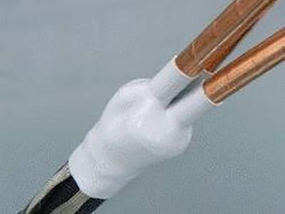
c) Install three-pronged gloves and cold shrink straight pipe
d) Slightly shrink the core rope of the “finger” part of the three-pronged glove, so that the three-pronged glove can be completely inserted into the root of the cable, then extract the core rope counterclockwise, shrink the neck first, and then shrink the three-core “fingers” in the same way.
e) Then sleeve the cold-shrinkable straight pipes respectively, overlap at least 15 mm with the “finger” part of the three-pronged glove, extract the core rope counterclockwise to shrink it, and complete the three-phase installation in sequence.
(14) end to straight pipe length verification
Check whether the length from the cable end to the cold-shrink straight pipe port meets the termination installation requirements. If it is less than the required length, the cold-shrink straight pipe needs to be shortened. If it meets the requirements, proceed to the following steps. When shortening the cold-shrinkable straight pipe, it must be circumscribed first, and then axially cut, and the copper shielding layer and other internal structures must not be damaged.
(15) Stripping of the metal shielding layer
Use PVC tape to temporarily fix and locate the peeling position of the copper shielding layer, tear the copper tape along the edge of the PVC tape, and flip it back along the constant force spring if there is a copper wire shielding. The outer semi-conductive shielding layer and insulating layer should not be damaged. The copper shielding fracture should be uniform and neat, without sharp corners and quick openings, and it is not allowed to let the sharp corners of the copper tape penetrate into the outer semi-conductive layer.
(16) Stripping of the outer semiconducting layer and the insulating layer
When processing the outer semi-conductive layer, firstly cut the ring and then longitudinally. The cutting depth is 2/3 of the thickness of the semi-conductive layer. Strip the semi-conductive layer from the ends respectively. Scrape off the glass. When the outer semi-conductive layer is cut circularly and longitudinally, the lower knife should not be too deep to avoid damage to the main insulation of the cable. It is required that the fracture of the outer semiconducting layer after stripping is neat and smooth, without sharp corners or burrs. When removing the top insulation, do not damage the cable conductors.
(17) Wrapping semi-conductive tape
Semi-overlapping and wrapping semi-conductive tape, starting from 5 mm on the copper shielding tape, wrapping to 5 mm on the main insulation, and then wrapping back to the beginning. The semiconductive tape needs to be fully stretched when wrapping to avoid air gaps between overlapping layers. The semiconducting tape port wrapping onto the main insulation should be very neat and sleek.
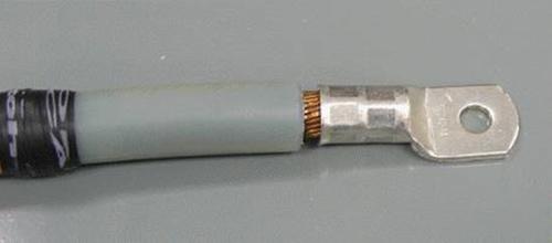
(18) Crimp filing terminal
According to the construction process requirements of the accessories, select the circular confining pressure, the hexagonal confining pressure, or the point pressure method for crimping. Before crimping, check whether the size of the cable terminal lug and the cable conductor match, select the cable terminal with the appropriate cross-section, and select the crimping pliers and mold of the appropriate tonnage according to the cross-section. After the crimping reaches a certain pressure or the mold is closed, keep the pressure for 10 to 15s, and then release the mold, and the terminals cannot be significantly bent after crimping. After the crimping is completed, if there are sharp corners, burrs, and edges on the terminals and conductors, they must be removed with a file and smoothed with sandpaper, and cleaned. When sanding terminals, cover the main insulation of the cable with newspaper or cloth to prevent metal shavings from falling on the main insulation. The nozzle crimping sequence should be from top to bottom.
(19) Grinding and cleaning of the main insulating surface
Grind the main insulation surface of the cable, first use 120# sandpaper for rough grinding, and then use 240# sandpaper for fine grinding. After grinding, there should be no knife marks or semi-conductive particles on the main insulation surface of the cable. The main insulation surface of the cable should be cleaned with anhydrous solvent, wiped from the insulation part to the direction of the semi-conductive layer, and must not be wiped back and forth, and must not be reused. The primary insulating surface must be dry and, if necessary, wipe with a clean lint-free cloth before proceeding to the next step.
(20) Apply silicone grease
Apply silicone grease on the junction of the semi-conductive tape wrapping end and the main insulation, and then apply the rest of the agent evenly on the main insulation surface.
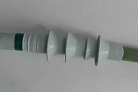
(21) Install cold shrink termination
a) Before installing the cold shrink termination, fill the gap between the termination and the main insulation of the cable with insulating waterproof tape. Clean the inside of the main body of the cold shrinkable termination, determine the starting positioning mark of the shrinkage according to the installation requirements, align the positioning mark, and pull the core rope backward counterclockwise to shrink the termination. Do not push it forward during the shrinking process to prevent curling.
b) Wrap the silicone rubber tape or install the end sealing tube
c) Starting from the termination tube, wrap the silicone rubber tape half-overlap to the termination, and then wrap it back to one layer. There is no need to stretch hard when wrapping the silicone rubber tape, just wrap it naturally.
d) If the end seal is achieved by using a cold shrink tube, pull out the core rope counterclockwise respectively to shrink the sealed tube to a predetermined position.
(22) Quality acceptance
a) Do a good job of on-site quality inspection and report filling in a timely manner, and strengthen process monitoring and quality sampling. Joint construction is a concealed project, and acceptance should be carried out during the construction process. Including the acceptance of joint preparation work, insulation treatment, conductor connection, cold shrink joint installation, grounding and sealing treatment, construction identification, and other items.
b) Final attachment acceptance generally includes two aspects: data and on-site physical inspection.
c) Data include joint installation records and quality assessment records, product qualification certificates provided by the manufacturer, test certificates and installation drawings, and other technical documents.
d) On-site physical inspection includes visual inspection, joint fixation, joint level deviation, etc.