When sourcing electrical wires and cables for projects in the United States, you will frequently encounter conductor sizes such as 12 AWG, 4 AWG, 4/0 AWG, and 500 kcmil. These specifications may look unfamiliar to buyers who usually work with metric conductor sizes, such as 2.5 mm², 25 mm², or 120 mm².
Understanding American Wire Gauge (AWG) is essential for electrical engineers, project contractors, equipment manufacturers, and cable procurement professionals who work with US electrical specifications. It helps buyers interpret technical documents, compare cable specifications, and communicate conductor size requirements with international manufacturers.
However, AWG is only one part of cable specification. It does not directly determine a cable’s voltage rating, ampacity, insulation type, or complete construction. These characteristics depend on additional technical requirements and applicable electrical standards.
In this guide, we explain what AWG means, how the system works, how to read an AWG wire size chart, how to convert AWG to mm², and how AWG compares with kcmil. We also cover the factors that buyers should consider when selecting electrical cables for industrial and power distribution projects.
1. What Is American Wire Gauge (AWG)?
American Wire Gauge, commonly abbreviated as AWG, is a standardized numbering system used to identify the size of electrical wire conductors. It is widely used in the United States and appears in many electrical product specifications, installation documents, and procurement requirements.
AWG is commonly used for copper and aluminum conductors in applications such as building wiring, control circuits, equipment connections, and certain power cables.
Typical examples include:
- 18 AWG: Used in some control circuits, signal wiring, and equipment wiring.
- 14 AWG: Used in certain building branch-circuit applications where permitted by the applicable electrical code.
- 12 AWG: Commonly specified for certain residential and commercial branch circuits.
- 4 AWG: Used in some larger-current circuits and equipment power connections.
- 4/0 AWG: Used in applications requiring substantially larger conductors.
These are general examples rather than universal recommendations. The appropriate conductor size depends on the actual load, installation conditions, conductor material, insulation temperature rating, and applicable electrical requirements.
What Does AWG Measure?
AWG identifies a conductor size through a standardized gauge number. Each gauge corresponds to a defined nominal conductor diameter and cross-sectional area for a standard solid round conductor.
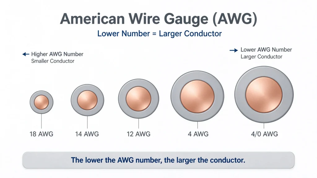
One of the most important rules to remember is:
The lower the AWG number, the larger the conductor. The higher the AWG number, the smaller the conductor.
For example, a 4 AWG conductor is substantially larger than a 14 AWG conductor.
AWG does not describe the entire cable construction. A finished cable may also include insulation, fillers, shielding, armor, and an outer sheath. Therefore, an AWG designation alone is not sufficient to specify a complete cable for a commercial or industrial project.
2. How Does the AWG System Work?
AWG uses a numerical scale to identify conductor dimensions. Unlike metric conductor sizing, which expresses cross-sectional area directly in square millimeters, AWG uses gauge numbers that correspond to specific conductor dimensions.
Common sizes include 18 AWG, 16 AWG, 14 AWG, 12 AWG, 10 AWG, and larger sizes such as 4 AWG and 2 AWG.
As the gauge number decreases, both conductor diameter and cross-sectional area increase. As the gauge number increases, both dimensions decrease.
What Do 1/0, 2/0, 3/0, and 4/0 AWG Mean?
For larger conductor sizes, the AWG system uses special designations that include zeros:
- 1/0 AWG, also called 0 AWG
- 2/0 AWG, also called 00 AWG
- 3/0 AWG, also called 000 AWG
- 4/0 AWG, also called 0000 AWG
These are standard AWG designations, not ordinary fractions. The more zeros in the designation, the larger the conductor.
For example, 1/0 AWG has a nominal cross-sectional area of approximately 53.5 mm², while 4/0 AWG has an area of approximately 107 mm².
For conductors larger than the common AWG range, US cable specifications often use kcmil. This unit is particularly relevant to larger power distribution conductors and industrial electrical installations.
3. AWG Wire Size Chart: Diameter and Cross-Sectional Area
An AWG wire size chart helps buyers compare conductor dimensions and understand how American wire sizes relate to metric measurements.
The following table provides approximate standard dimensions for common AWG sizes.
| AWG Size | Nominal Diameter (mm) | Nominal Cross-Sectional Area (mm²) |
|---|---|---|
| 18 AWG | 1.02 | 0.823 |
| 16 AWG | 1.29 | 1.31 |
| 14 AWG | 1.63 | 2.08 |
| 12 AWG | 2.05 | 3.31 |
| 10 AWG | 2.59 | 5.26 |
| 8 AWG | 3.26 | 8.37 |
| 6 AWG | 4.11 | 13.3 |
| 4 AWG | 5.19 | 21.2 |
| 3 AWG | 5.83 | 26.7 |
| 2 AWG | 6.54 | 33.6 |
| 1 AWG | 7.35 | 42.4 |
| 1/0 AWG | 8.25 | 53.5 |
| 2/0 AWG | 9.27 | 67.4 |
| 3/0 AWG | 10.4 | 85.0 |
| 4/0 AWG | 11.7 | 107 |
How to Read an AWG Wire Size Chart
Consider the difference between 12 AWG and 4 AWG:
- 12 AWG has a nominal cross-sectional area of approximately 3.31 mm².
- 4 AWG has a nominal cross-sectional area of approximately 21.2 mm².
The 4 AWG conductor therefore has approximately 6.4 times the cross-sectional area of the 12 AWG conductor.
A larger conductor generally has lower electrical resistance when conductor material, temperature, and other relevant conditions are comparable. However, this does not mean that its allowable current is automatically 6.4 times greater.
Ampacity depends on thermal conditions, insulation ratings, installation methods, the number of current-carrying conductors, and the requirements of the applicable electrical code.
Important note: The diameter values in this table refer to approximate nominal dimensions for standard solid round conductors. Stranded conductors can have different strand arrangements, strand diameters, and compaction characteristics. The finished cable’s outside diameter will also be larger because of insulation and other cable components.
4. AWG to mm² Conversion Chart
AWG and mm² are two different ways to express conductor size.
- AWG identifies conductor size through a gauge number.
- mm² expresses the conductor’s cross-sectional area directly in square millimeters.
AWG is common in US electrical specifications, while mm² is widely used in metric-based cable standards and international procurement.
The following table provides approximate comparisons between common AWG sizes and nearby metric conductor sizes.
| AWG Size | Approximate Area (mm²) | Nearby Metric Size for Reference |
|---|---|---|
| 18 AWG | 0.823 | 0.75 mm² range |
| 16 AWG | 1.31 | 1.5 mm² range |
| 14 AWG | 2.08 | 2.5 mm² range |
| 12 AWG | 3.31 | 4 mm² range |
| 10 AWG | 5.26 | 6 mm² range |
| 8 AWG | 8.37 | 10 mm² range |
| 6 AWG | 13.3 | 16 mm² range |
| 4 AWG | 21.2 | 25 mm² range |
| 2 AWG | 33.6 | 35 mm² range |
| 1/0 AWG | 53.5 | 50 mm² range |
| 2/0 AWG | 67.4 | 70 mm² range |
| 3/0 AWG | 85.0 | 95 mm² range |
| 4/0 AWG | 107 | 120 mm² range |
These metric sizes are comparison references, not exact equivalents. AWG and metric conductor sizing systems do not always match one-to-one.
For example, 4 AWG has a nominal area of approximately 21.2 mm², not 25 mm². Similarly, 4/0 AWG has a nominal area of approximately 107 mm², not 120 mm².
A nearby metric size should not automatically be treated as an interchangeable replacement. Engineers and buyers should also verify conductor resistance, material, ampacity, terminal compatibility, cable construction, and applicable standards.
How Is Conductor Cross-Sectional Area Calculated?
For a solid circular conductor, the cross-sectional area can be calculated using its diameter:
A = π × d² ÷ 4
Where:
- A is the cross-sectional area.
- d is the conductor diameter.
- π is approximately 3.1416.
For example, a solid round conductor with a diameter of approximately 2.05 mm has a calculated cross-sectional area of about 3.30 mm², which is close to the nominal 3.31 mm² area of 12 AWG.
This calculation is useful for understanding the relationship between diameter and area. However, it should not replace verification against the applicable conductor standard and manufacturer’s technical data, especially for stranded, compacted, or specially constructed conductors.
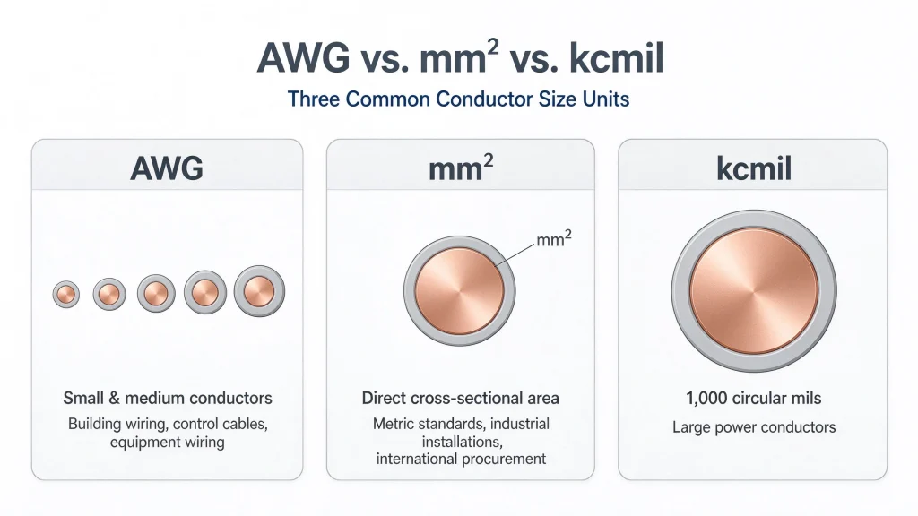
5. AWG vs. mm² vs. kcmil: What Is the Difference?
AWG is not the only conductor sizing system used in the United States. For larger power conductors, kcmil is also widely used.
Understanding the differences between these three units helps international cable suppliers interpret customer specifications more accurately.
AWG
AWG is commonly used for small and medium conductor sizes. It appears in building wiring, control cables, equipment wiring, and various electrical product specifications.
mm²
Square millimeters express conductor cross-sectional area directly. This measurement is widely used in metric-based electrical standards, industrial installations, and international cable procurement.
kcmil
The term kcmil means one thousand circular mils. A circular mil is a unit used to express the cross-sectional area of a circular conductor.
One kcmil equals 1,000 circular mils.
Common approximate conversions include:
| Conductor Size | Approximate Area (mm²) |
|---|---|
| 250 kcmil | 127 |
| 350 kcmil | 177 |
| 500 kcmil | 253 |
| 750 kcmil | 380 |
These values are rounded conversions for comparison. Actual product specifications should be confirmed against the relevant standards and manufacturer documentation.
In US cable specifications, larger power conductors may be identified using kcmil rather than AWG. This is particularly relevant in power distribution, industrial electrical systems, and large equipment connections.
For international cable manufacturers, familiarity with AWG, mm², and kcmil makes it easier to review US customer drawings, bills of materials, and cable data sheets.
6. Does AWG Determine Cable Ampacity?
No. AWG identifies conductor size, but it does not independently determine allowable current-carrying capacity.
Ampacity is the current a conductor can carry continuously under specified conditions without exceeding the applicable temperature limitations.
The allowable ampacity of an electrical cable depends on several technical factors.
6.1 Conductor Material
Copper and aluminum are common electrical conductor materials.
Under comparable conditions, copper generally has lower electrical resistance than aluminum for the same cross-sectional area. Consequently, copper and aluminum conductors may require different sizes to meet a particular electrical design requirement.
Aluminum is lighter and can be advantageous in certain power distribution applications. The final choice should consider electrical performance, conductor weight, connection requirements, cost, and project specifications.
6.2 Insulation Material and Temperature Rating
Cable insulation affects the permitted conductor operating temperature and the cable’s suitability for a particular application.
Common insulation materials include PVC, XLPE, and various rubber-based compounds. Their thermal, mechanical, and environmental properties differ.
However, insulation material alone is not enough to establish ampacity. The actual temperature rating, cable construction, applicable standard, and installation conditions must also be verified.
6.3 Installation Method and Heat Dissipation
Installation conditions influence how effectively a cable releases heat.
Examples include:
- Installed in free air.
- Installed in conduit or trunking.
- Installed in cable trays.
- Buried underground.
- Grouped with other current-carrying cables.
Different installation methods provide different heat-dissipation conditions. Therefore, two cables with the same AWG size may have different allowable ampacities when installed under different conditions.
6.4 Ambient Temperature and Number of Conductors
Higher ambient temperatures may reduce the allowable ampacity of a cable. Grouping multiple current-carrying conductors can also require adjustments under the applicable electrical code.
In addition, terminals, connectors, and equipment connection points may have temperature limitations that affect the permitted current for the complete circuit.
When consulting an AWG ampacity chart, always check the underlying standard, conductor material, insulation temperature rating, ambient temperature, installation method, and applicable correction factors.
A current rating from one table should not be applied automatically to every cable installation.
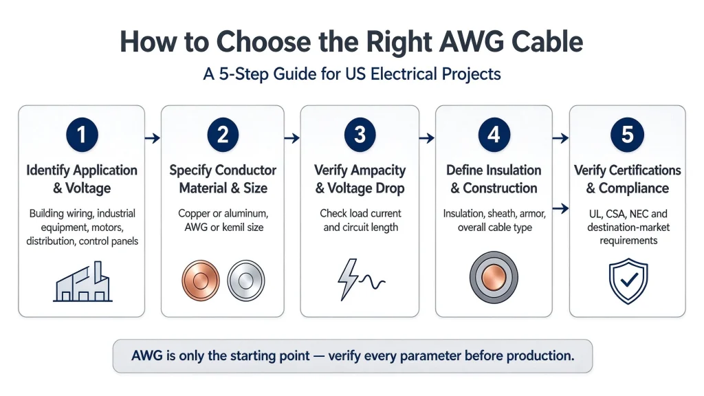
7. How to Choose the Right AWG Cable for a US Electrical Project
For electrical contractors, equipment manufacturers, and cable procurement teams, AWG is only the starting point for cable selection. A complete specification requires several additional checks.
Step 1: Identify the Application and System Voltage
Determine where the cable will be used, such as:
- Building electrical wiring.
- Industrial equipment power supply.
- Motor and machinery connections.
- Power distribution systems.
- Control panels and automation equipment.
- Renewable energy or other specialized electrical installations.
Different applications may have different voltage ratings, insulation requirements, mechanical protection needs, environmental conditions, and certification requirements.
Step 2: Specify the Conductor Material and Size
Confirm whether the project requires copper or aluminum conductors and identify the required AWG or kcmil size.
If the customer provides a metric conductor size, an AWG to mm² conversion chart can help establish an initial comparison. The final specification should nevertheless be confirmed by both parties before production.
Step 3: Verify Ampacity and Voltage Drop
Determine the required ampacity based on the actual load, installation conditions, and applicable electrical code.
For long cable runs, voltage drop should also be evaluated. A conductor may satisfy an ampacity requirement but still produce excessive voltage drop under a particular load and circuit length.
Therefore, conductor size should not be selected based on current alone.
Step 4: Define Insulation, Sheath, and Cable Construction
Specify the required cable construction according to the application.
Important parameters may include:
- PVC or XLPE insulation.
- Single-core or multicore construction.
- Shielding requirements.
- Armoring requirements.
- Oil, UV, moisture, or other environmental resistance.
- Required overall cable diameter or installation limitations.
AWG does not provide this information. These details must be included separately in the cable specification.
Step 5: Confirm Applicable Standards and Certifications
US projects may require compliance with the National Electrical Code (NEC), relevant UL requirements, or other applicable standards and certifications. The exact requirements depend on the cable type, intended use, installation location, and project documentation.
A cable does not automatically meet all US market requirements simply because its conductor has a particular AWG size.
For export projects, buyers and manufacturers should confirm the applicable standards, testing requirements, certification scope, and required technical documentation before placing an order.
8. AWG in US Cable Procurement: What International Buyers Should Know
For international cable suppliers, understanding AWG is an important part of communicating effectively with US customers.
A US customer may include the following terms in an inquiry or technical document:
- 12 AWG copper wire
- 4 AWG aluminum conductor cable
- 4/0 AWG power cable
- 500 kcmil aluminum cable
- AWG wire size chart
- AWG to mm² conversion
These terms help establish the requested conductor size, but they do not define the complete cable product.
For example, if a customer requests 4/0 AWG power cable, the supplier should confirm additional details, including:
- Rated voltage.
- Copper or aluminum conductor.
- Number of cores.
- Insulation and sheath materials.
- Cable construction and protection requirements.
- Applicable standards and certifications.
- Installation environment.
- Required quantity and delivery schedule.
If the customer provides only an AWG designation, requesting a complete cable data sheet or project specification can help prevent misunderstandings about conductor dimensions, product construction, and compliance requirements.
For cable manufacturers serving international markets, the ability to interpret AWG, mm², and kcmil accurately can improve technical communication, quotation accuracy, and procurement efficiency.
9. Frequently Asked Questions About AWG
AWG stands for American Wire Gauge. It is a standardized numbering system used to identify electrical conductor sizes.
No. A higher AWG number generally means a thinner conductor. For example, 14 AWG is smaller than 12 AWG, while 4 AWG is larger than 6 AWG.
12 AWG has a nominal cross-sectional area of approximately 3.31 mm². It is close to some commonly used metric sizes but is not automatically interchangeable with a different metric conductor size.
4/0 AWG has a nominal cross-sectional area of approximately 107 mm². It is not exactly equivalent to 120 mm². Any substitution must be evaluated against the project’s technical requirements.
Not without verification. They are different conductor sizing systems, and nearby sizes may differ in cross-sectional area, electrical resistance, ampacity, and product construction. The final selection should follow the confirmed project specification and applicable standards.
kcmil is a unit used to express the cross-sectional area of larger circular conductors. One kcmil equals 1,000 circular mils. It is commonly encountered in US specifications for large power conductors.
No. Ampacity also depends on conductor material, insulation temperature rating, ambient temperature, installation method, the number of current-carrying conductors, terminal limitations, and applicable electrical requirements.
No. AWG describes the conductor size, not the finished cable’s overall diameter. The overall diameter depends on the insulation, number of cores, fillers, shielding, armor, and outer sheath.
Provide the intended application, system voltage, conductor material and size, number of cores, insulation and sheath requirements, installation conditions, applicable standards, testing requirements, and delivery specifications. A qualified cable supplier can use these details to confirm the appropriate cable construction.
Conclusion
American Wire Gauge is an essential part of understanding electrical wire and cable specifications in the United States. Learning how to read an AWG wire size chart, convert AWG to mm², and interpret kcmil specifications helps engineers, contractors, procurement professionals, and cable manufacturers communicate conductor size requirements more effectively.
However, conductor size is only one part of cable selection. Ampacity, voltage drop, conductor material, insulation temperature rating, installation conditions, cable construction, and applicable standards must also be considered.
Looking for a cable supplier for your power distribution or industrial project?
Share your required conductor size, rated voltage, application, cable construction, and applicable standards with our team. We can review your requirements and help identify the appropriate cable specifications for your project and supply needs.